Hackworth Valve Gear - Bill Perry
Background
:
As a bit of
background, my
I wrote the
article based on my experiences with
Regards. Bill Perry
Article :
Having visited
several shows, it is interesting to see the various set-ups of the Hackworth
Valve Gear on several “Sweet Peas”. It appears that despite all the articles
written about it people are unsure of the setting up procedure. This was
confirmed by a talk I had with a gentleman on one stand.
There is a method I have evolved, which, provided everything has been built to
the drawings, does not need any mathematics. This has been tested on two Sweet
Peas with good results.
1.
There must be no slop in any of the components of the
valve gear.
2.
Remove the cover on the valve chests.
3.
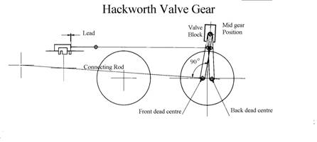
Set the wheels on the back dead centre, i.e. with the
crankpin in line with the connecting rod, not at 90 degrees.
4.
Place a small setsquare on the connecting rod and
check that the side of the valve block is at 90 degrees with the valve in mid
gear. Any adjustment required can be made by fitting packing between the
operating lever at the bottom of the valve block.
5.
Move the valve gear lever backwards and forwards and
check that the valve rod does not move. Adjust the wheel height to correct this
if required.
6.
Move the wheels to front dead centre and repeat step
5. If everything has been made correctly no adjustment should be required.
7.
Repeat the exercise on the other side of the engine.
Note that the valve block angle should be at 90 degrees if the blocks have been
set parallel.
8.
Any adjustment to the wheel height can have a small
effect on the other side due to the overhang so repeat step 5 again
9.
Now with the gear set at mid gear move the engine and
check that the valve shows an equal port opening on both sides of the engine.
Adjust the setting if required.
10.
Now with the valve gear set in forward, move the
engine and check where the valve port is just uncovered. Ideally with
everything tight this should be about 2 degrees before the dead centre. Check
at both front and back centres.
Note the valve block should not move more the 30 degrees about the mid point
when selecting forward or reverse.
11.
Move the valve gear to reverse and repeat the port
opening check while moving the engine in reverse. This should again be about 2
degrees.
12.
If the setting is at the dead centres the valve needs
shortening slightly equally at both ends, or as the linkage wears the valve
will be opening after the dead centres.
13.
Now link up the valve in forward and reverse and
observe the valve openings as before. The valve openings should be equal as
above, but with shorter cut-off.
What other modifications can be done to improve the
long-term operation of Sweet Pea?
1.
Replace the valve block in the slides with a bright
key steel one instead of the phosphor bronze one and lubricate with molybdenum
grease on fitting.
2.
The operating lever for the valve block should
connect to the top of the valve block. Examine the geometry with the valve in
full forward. The operating lever is trying to stop the valve block from moving
backwards and forwards with the engine operating. I know this requires
modification to the reversing lever to put the linkage below the pivot point,
but it is the ideal.
3.
Now that you have an engine that can link up, the
lubricator drive may not work if connected to the valve rod. A small bracket
connected to the bottom of the Hackworth valve link just above the crankpin
will provide a constant motion to the lubricator arm.